Notes from 'Nanite GPU Driven Materials'
These are my notes from “Nanite GPU Driven Materials” by Graham Wihlidal. He delivered the presentation at GDC 2024, and the slides are now accessible as a PDF file. As you can download the original text, there is no reason to read this article. Still, some might find it useful.
I do not work for or are affiliated with Epic Games in any way. These are my personal notes that I have made public. If I say “Unreal Engine does X” it’s a shorthand.
First, we are going to see the initial Nanite pipeline as presented in “Nanite A Deep Dive” by Brian Karis. We will discuss problems and inefficiencies. We will then use programmable rasterization steps to handle e.g. alpha masks, two-sided materials, and vertex animation. Shading using compute shaders follows next. We will end with a discussion on the new DirectX 12 Work Graphs API.
I assume the reader already has a working knowledge of GPU-driven rendering and meshlets. I will skip any explanation of two-pass occlusion culling. It is important but contributes nothing to what’s described. I’ve also tried to skip Nanite-specific stuff to make it more accessible, although software rasterizer plays a big role in this post. This also applies to terms like “cluster”. For Nanite, it refers to a combination of meshlet and per-instance data. I will usually stick to “meshlet” instead.
Feel free to send me an email if you see any errors. Some stuff was simplified, but that’s to keep the text brief. Please do not email me anything not derived from the publicly accessible materials.
Nanite in UE 5.0 (2022)
The presentation starts with the graphic pipeline overview as presented in “Nanite A Deep Dive” by Brian Karis. Here is a simplified version familiar to everyone who worked with GPU-driven rendering (two-pass occlusion culling skipped for clarity):

Simplified pipeline for GPU-driven rendering. See slide 12 for the full Nanite version.
For the hardware/software rasterizer split, decide based on e.g. projected size of the meshlet bounding sphere. Both rasterizers write to the visibility buffer using 64-bit atomic operations (depth << 32 | clusterId). However, UE5 has shader graphs, which leads to 2 immediate problems:
- Some materials need special code to decide if/how they write to the visibility buffer. Think e.g. alpha masks, two-sided materials, vertex animations, etc.
- You have a visibility buffer and the referenced triangles are shaded using shader graphs. How do you swap between materials?
In UE 5.0, the first problem was not addressed. Objects with special materials were rendered without Nanite. We will see the solution in the “Programmable Raster” section.
Nanite’s team solved problem 2 by rendering many fullscreen triangles, one for each material. Each draw has to find all the pixels that use its material. As draw commands are added from the CPU, some commands do nothing. E.g. the renderer does a draw with materialId for a chair. But, after GPU culling, there are no pixels with this material. What if you did a pipeline state object (PSO) or descriptor change for nothing?
Known optimization writes materialId to SV_Depth. The fullscreen triangle can test DEPTH_EQUALS to reject pixels with the early depth-stencil test. This approach was used in Eidos Montreal’s Dawn Engine:
“In an initial geometry pass, all mesh instances, that pass the GPU culling stage, are rendered indirectly and their vertex attributes are written, compressed, into a set of geometry buffers. No material specific operations and texture fetches are done (except for alpha-testing and certain kinds of GPU hardware tessellation techniques). A subsequent full screen pass transfers a material ID from the geometry buffers into a 16-bits depth buffer. Finally, in the shading pass for each material, a screen space rectangle is rendered that encloses the boundaries of all visible meshes. The depth of the rectangle vertices is set to a value that corresponds to the currently processed material ID and early depth-stencil testing is used to reject pixels from other materials.”
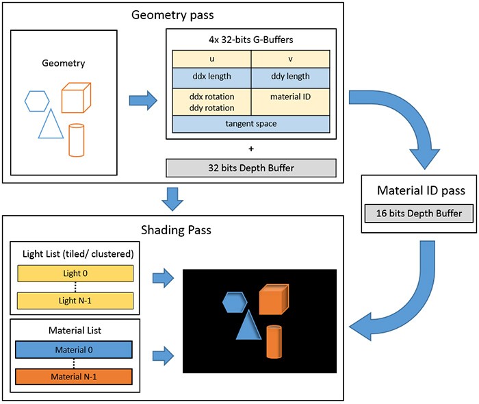
The current version of the original article is missing the crucial image. I’ve retrieved it from web.archive cache. All rights to the image belong to Eidos Montreal.
Later on, the technique was optimized using 64x64 pixel tiles. There are 2 possible approaches.
First, compute a list of materials for each tile (think Map<TileId, List<MaterialId>>). Then, for each material, draw all tiles. The vertex shader returns bogus coordinates if the tile does not contain pixels affected by the current material. Or the usual NDC tile coordinates if it does. With a few memory reads, we can skip depth tests for 64x64 pixels.
Or, create a list of tiles per material (think Map<MaterialId, List<TileId>>). We still use separate draw indirects for each material. However, the draw index is used to grab an entry from the current material’s tile list. Each entry is mapped to the tile’s location.
Programmable Raster in UE 5.1 (2022)
See “Bringing Nanite to Fortnite Battle Royale in Chapter 4” for extra info beside the slides.
As mentioned above, Nanite in UE5 did not handle the following material properties:
- Alpha masking (e.g. grass, trees). Conditionally skip writing to the visibility buffer based on texture.
- Leaves in Fortnite seem to still use geometry instead of alpha masks.
- Two-sided materials. Write to visibility buffer despite “incorrect” triangle winding.
- Pixel depth offset. Modify written depth.
- Vertex animation (UE5’s WPO - world position offset, e.g. wind, animated reactions). Modify write coordinates inside the visibility buffer.
- Custom UVs. Not explained.
- …
All these effects interact with the visibility buffer or change values written to it. Looking back at the Nanite pipeline, we need to make rasterization stages configurable.

New pipeline with programmable raster passes. We will have to create many variants of software and hardware rasterizers.
As we have both hardware (HW) and software (SW) rasterization, we have to handle all effects in both variants. This number can explode if you need separate descriptors.
For two-sided materials, HW rasterization requires PSO change from CULL_BACKFACE to CULL_NONE. For the SW raster, you can swap 2 vertex indices with each other to revert the winding if needed.
For alpha masking, HW rasterization can sample the texture. SW rasterization requires additional barycentric coordinates, derivatives, and mipmap calculation first.
A unique combination of material properties and descriptors that affect rasterization is called a raster bin. Notice that the CPU, once again, will dispatch/draw indirect all possible combinations of raster bins. It does not know what has made through the GPU culling. If material exists in the scene we dispatch both HW and SW rasterizer for it. It might even happen that all the material’s meshlets are processed by only one technique, rendering either HW or SW rasterizer jobless.
Meshlets might also contain triangles with different materials.
We now have to create compute passes that, for each raster bin, output a list of meshlets.
Sorting into raster bins
Meshlet culling produces 2 lists of meshlets - one for hardware and one for software rasterizer. All we need to do is to sort both lists into raster bins. This way, draw/dispatch for each shader bin will fetch its slice of the list.
If you’ve ever done GPU sorting into bins, you already know the implementation. If you don’t, here is code from my Frostbitten hair WebGPU that sorts screen tiles based on the number of hair segments:
As you can see, it’s not complicated. In UE5 there are 3 stages:
- Classify dispatches a thread per cluster. It increments a global counter for each raster bin present.
- Reserve dispatches a thread per raster bin. Calculates memory offsets in the array that contains
vec2<u32>elements (i32 clusterIdx,i16 triangleIdx start,i16 triangleIdx end).- Example implementation: there is a global
offsetCounter. Each raster bin atomically adds its cluster count. This functions as a memory space reservation. - Also initializes indirect arguments for rasterization draws/dispatches.
- Example implementation: there is a global
- Scatter dispatches thread per cluster. Fills the array based on reserved memory offsets.
Note that each dispatch/draw will have to know its slice of the meshlet list - both offset and count. I’ve also hand-waved some other issues - see slides. E.g. you can use async compute. The barrier configuration seems atypical.
This is enough for each draw/dispatch to rasterize its assigned triangles.
Compute shading in UE 5.4 (2024)
We will now look at the later stage of the pipeline - shading.

Executing shader graphs per material to write to the GBuffer.
In UE 5.4, all the shading was moved to compute shaders - see slides 59 and 60 for potential problems. While this approach has some performance advantages over fullscreen triangles (dispatches are cheaper for empty workload, no context rolls, access to workgroups, no longer bound by 2x2 quads), the naive implementation will be slower than the one from UE 5.0. Let’s see how sorting pixel locations into shading bins can improve this.
Sorting into shading bins
The slides do not define a shading bin. Let’s use the simplest definition: a unique material (we are not even considering different triangles, depth discrepancy, etc.). We will revisit this definition later. Our goal is to generate a list of pixel locations for each material. This requires an allocation of size screenPixelCount * vec2<u32>. The algorithm is like one for raster bins and has the following stages:
- Count dispatches a thread per 2x2 pixel region (a quad). Counts the number of pixels per shading bin (material).
- Reserve dispatches a thread per shading bin. Calculates memory offsets in the before-mentioned array. This functions as a memory space reservation.
- Also initializes indirect arguments for each shading dispatch.
- Scatter dispatches a thread per 2x2 pixel region. Fills the array with pixel locations based on reserved memory offsets.
- Dispatched as 8x8 workgroup called block (so 16x16 pixels). Threads are assigned to quads inside the workgroup using Morton code.
- All pixels for a block that share the same shading bin are placed next to each other in the final array. Thus, for each block:
- Count pixels from a particular shading bin.
- Execute a single atomic add for the whole workgroup.
- Broadcast inside the workgroup the start offset returned from the atomic add.
- Each thread calculates offsets into the array and writes.
- Repeat for all shading bins in the block.
You might have seen nearly the same algorithm in John Hable’s “Visibility Buffer Rendering with Material Graphs”. I’ve added comments relevant to UE 5.4’s implementation.
With this, our memory array of size screenPixelCount * vec2<u32> contains pixel locations sorted by material. Notice that two u32 is more than enough. Since each thread processes a 2x2 quad, additional Variable Rate Shading (VRS) info is added. Slide 73 calls this a quad write mask. We have enough data to make a VRS decision (slide 101) for all 4 pixels.
On slide 68 there is a note about Delta Color Compression (DCC). I’m not sure how this plays with the rest of the algorithm, especially VRS.
Shading passes
We are finally ready to evaluate shader graphs to populate GBuffer. The simplest solution is, for each material, to execute an indirect dispatch where 1 thread == 1 pixel. Set the push constants (Vulkan) or root constants (DirectX 12) to provide the materialId used to fetch a list of affected pixels (requires an additional level of indirection). You might notice we still have dispatches that will not change any pixels. The CPU only knows that the material exists in the scene. It does not know that all affected triangles might have been culled. It’s the 3rd time we have encountered this problem.
Quads optimization
As the scatter stage assigned a thread per 2x2 quad, if all 4 pixels share the same material, they will be stored next to each other. Shading pass can detect this using the quad write mask and use it for optimizations. E.g. you still have to calculate gradients (ddx/ddy/fWidth/mipmaps, see slides 73-86). I think such special 2x2 encoding optimization is presented on slide 88.
Or we could try to implement simple Variable Rate Shading. If all 4 pixels share the same material, the scatter pass would store only the top left pixel with an appropriate quad write mask (instead of all 4 pixels). You don’t even need to dispatch threads for these 3 skipped pixels (change in indirect dispatch arguments). If you want, you can extend this to handle special cases for 2x1 and 1x2. See slide 104 for visual examples.
I recommend John Hable’s “Software VRS with Visibility Buffer Rendering” if you need a refresher on quad utilization and helper lanes.
Morton code assignments
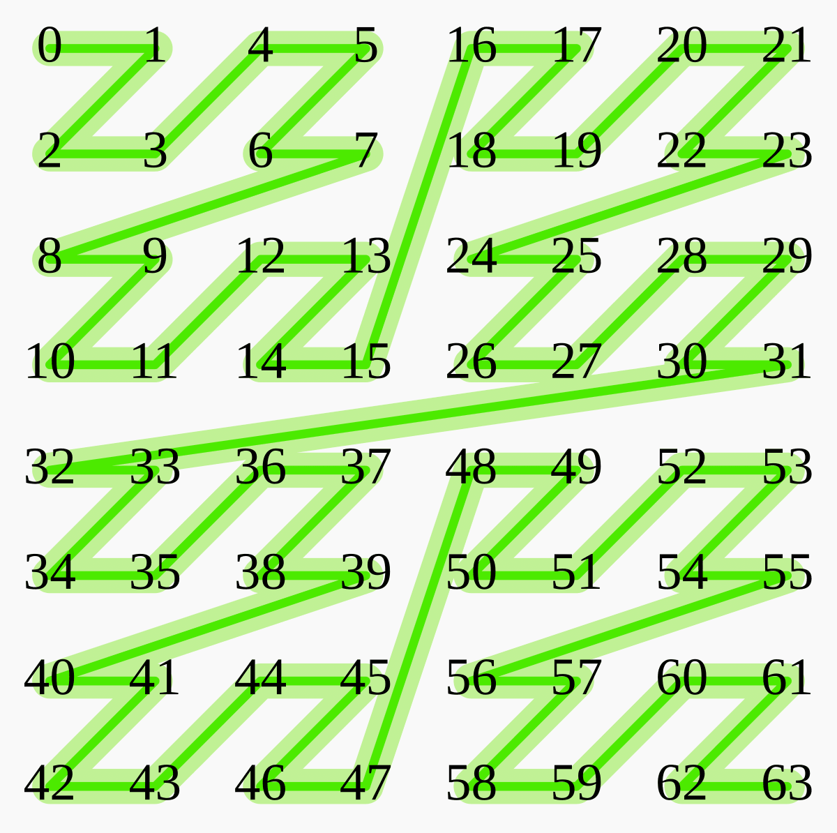
Using Morton code to assign indices to 2x2 quads preserves locality. Image based on work by David Eppstein originally published on Wikipedia and modified under CC0 license.
In the scatter phase, the threads are assigned to quads using Morton code. Each number in the above diagram represents a 2x2 quad. Therefore, threads 0, 1, 2, and 3 are assigned to a 4x4 pixel area. Each thread can detect if its quad contains only a single material. By broadcasting the values inside the workgroup we can detect bigger patches:
- Four consecutive (aligned to 4) threads sharing the same material indicate a 4x4 pixels VRS opportunity. E.g.
- Threads 0, 1, 2, and 3.
- Threads 4, 5, 6, and 7.
- …
- Threads 60, 61, 62, and 63
- Sixteen consecutive (aligned to 16) threads sharing the same material indicate an 8x8 pixels VRS opportunity. These are:
- Threads 0-15.
- Threads 16-31.
- Threads 32-47.
- Threads 48-63.
Locality in shading bins
Let’s go back to the definition of shading bins, this time using slide 69:
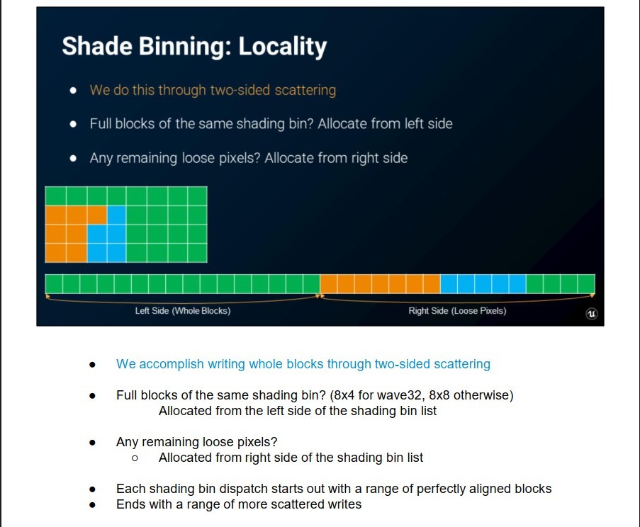
Slide 69 from the presentation.
Instead of a list of pixels per material, the array seems to be split based on the number of pixels of the same material in a block. Blocks containing only a single materialId are allocated at the front of the list. Write the leftover “standalone” pixels at the back.
I would assume this achieves the following:
- better data locality,
- easier to detect bigger blocks of the same material (VRS?),
- maybe better scheduling as most of the work is executed upfront?
I have to say that this setup looks a bit strange. The reasoning is probably clear to people who have already implemented such systems.
At this point, the presentation goes deeper into Variable Rate Shading. We’ve already discussed most of the ideas.
Empty bin compaction with work graphs
We are back at slide 109.
We have already encountered the same problem 3 times: empty indirect draws and dispatches. The UE 5.0’s implementation draws fullscreen triangles for each material. They produced no pixels if their meshlets were culled. In raster binning, we had software and hardware rasterizer commands that processed 0 meshlets. Again, some meshlets were culled. Or maybe all were assigned to software rasterizer, rendering hardware rasterizer useless? In compute shading we once again did empty dispatches for materials that never affected anything.
If the GPU is already doing something, the empty dispatches might not be a problem. Unfortunately, according to the screenshots, sometimes e.g. 3075 shading bins out of 3779 can be empty (81%).
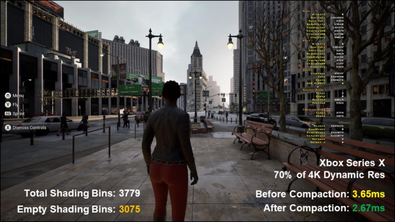
Slide 130 from the presentation. Out of 3779 shading bins, 3075 were empty (81%). Empty bin compaction saved nearly 1 ms.
The presentation provides a solution for consoles. Epic Games also tried to use ID3D12GraphicsCommandList::SetPredication() on DirectX 12, but the PSO (and descriptors) change proved too costly.
The solution (as some people have heard from the news) is to use DirectX 12 Work Graphs. All I know is that it allows you to dispatch/schedule a separate shader from another.
Here is a quote by Graham Wihlidal from the official release of D3D12 Work Graphs 6 months ago:
”(…) With Work Graphs, complex pipelines that are highly variable in terms of overall “shape” can now run efficiently on the GPU, with the scheduler taking care of synchronization and data flow. This is especially important for producer-consumer pipelines, which are very common in rendering algorithms. The programming model also becomes significantly simpler for developers, as complex resource and barrier management code is moved from the application into the Work Graph runtime. (…)”
And here is a screenshot from relevant DirectX-Specs introduction:
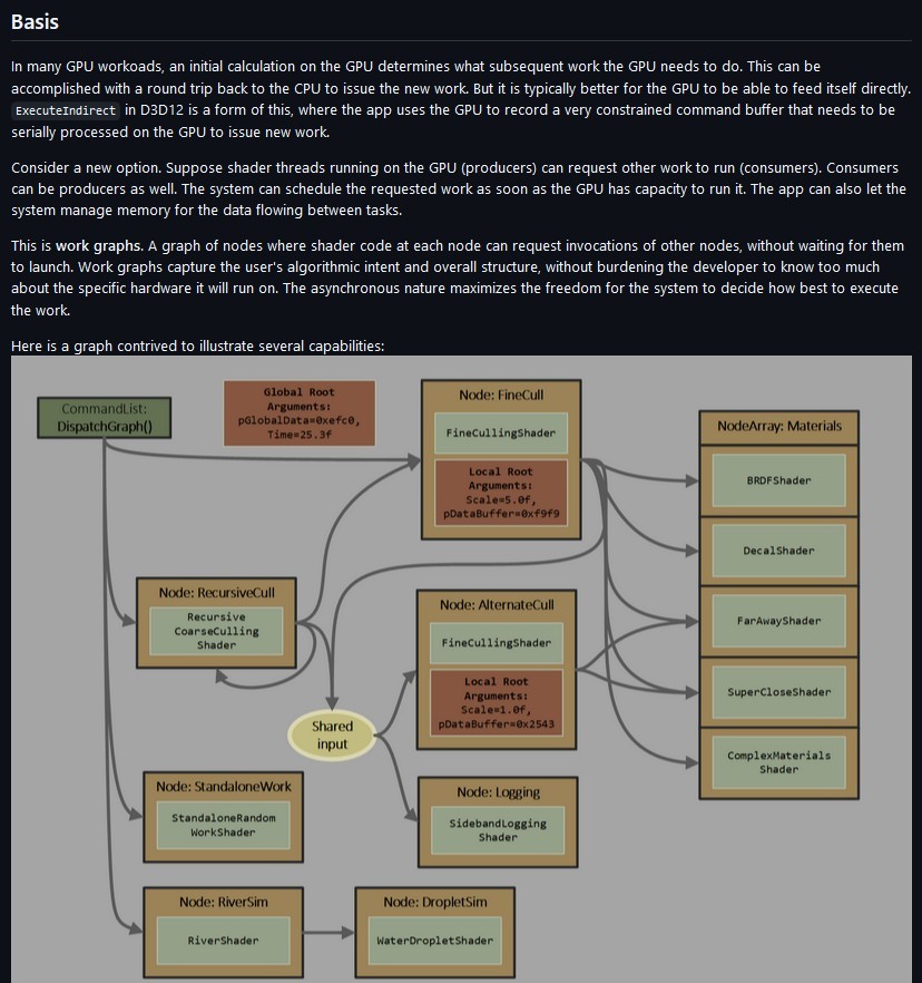
Preamble to DirectX 12 Work Graphs specification.
That sounds like a good fit to solve the problem. I assume other parts of Nanite might make use of it too.
Work graphs in Vulkan
A day after this article was published, VK_EXT_device_generated_commands was released (Vulkan 1.3.296).
Summary
Originally, I’d only read the presentation to know how Nanite was extended. Yet most of the covered topics can be broadly applied.
The programmable raster was not surprising. Once you realize “alpha masks can be implemented by not writing selected pixels to the visibility buffer”, most of the solution falls in place. Of course, there are more complex use cases. Converting the shader graph system (or just affected properties) was probably a lot of work.
The compute shading and Variable Rate Shading are (for me) a bit too complex and far removed from the initial Nanite problem. Remember, I look at this from the perspective of a tiny web app, which is already limited by a lack of 64-bit atomics and early depth-stencil tests.
The DirectX 12 Work Group API thing was interesting. I heard the news when it was first released. It’s nice to know why this solution exists.